Energy Saviours: Part 5
Tom Baxter looks at the parasitic load challenge of CCS

TO deliver net zero in the UK, carbon capture and storage (CCS) at scale is seen as a key enabler by most commentators and regulators.1 However, deploying CCS adds an additional power load, reducing the efficiency of the power station. According to the IPPC2, for a CCS plant on a combined cycle gas turbine power station, the additional power required will be in the range 11-22%. Deploying energy-efficient CCS facilities is therefore a key aspect of CCS design.
This article presents the equipment and unit operations associated with CCS, highlighting the main energy users, and looking at options for energy saving.
CCS plant
The following describes a typical CO2 capture plant on a fossil fuel power station.
Flue gas from the power station is cooled, and the cooled gas feeds a blower that increases the pressure sufficient to overcome the pressure drop in the downstream CO2 removal plant.
CO2 removal and solvent regeneration uses an aqueous amine solution, typically monoethanolamine (MEA). A counter-flow absorber is used in which the lean MEA solution reacts with the CO2. The CO2-rich MEA is taken from the absorber to a stripper where the reaction is reversed – CO2 is released from the rich amine by the application of heat. The lean amine stripped of CO2 is continuously returned to the absorber.
Figure 1 shows a simplified PFD of the blower and amine plant.
CO2 from the amine stripper is compressed in multiple stages to typically 110–120 bar, where it is supercritical. Part way along the compression train the CO2 is dehydrated. Water removal prevents corrosion and formation of hydrates (ice-like solid clathrates of CO2 and water) within the sequestration pipeline system.
Dehydration is facilitated by molecular sieves. Here water in the CO2 stream is adsorbed onto a solid alumina-silicate. This is a timer-controlled batch process where one bed is adsorbing whilst another bed, one that has previously adsorbed water, is being regenerated by applying heat. The bed is typically heated to 275oC to drive off the adsorbed water. Once the heating cycle is complete, the bed is cooled and returned to service.

Figures 2 and 3 show typical compression and dehydration PFDs. The last stage of CO2 pressure boosting is a pump, since CO2 at high pressure behaves more like an incompressible liquid.

On review of the CCS configuration it is clear that there are some large energy consumers: the flue gas blower, the amine regenerator, CO2 compressors, and the molecular sieve regeneration heaters. These introduce a parasitic load and consequently lower the overall power plant generating efficiency.

Although application specific, Table 1 shows a typical parasitic power share of the key CCS systems.
Taking the three main energy users in turn, the following describes and quantifies potential energy-saving opportunities.

Flue gas blower
Axial flow compressors are ideally suited to this high flow, low head application. Note that with the blower suction operating close to atmospheric pressure, the volume flow is very large, hence the significant power requirement. For a 400 MW generator the flowrate will be in the range 500–1,000 Am3/s.
The power for the blower can be estimated from the polytropic head expression.
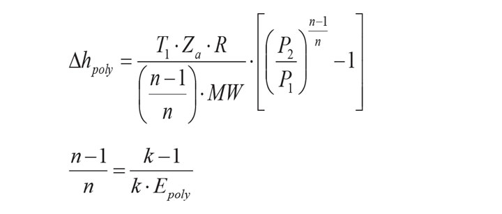
Power relationship:

Where:
∆hpoly = Polytropic head (kJ/kg)
T = Temperature (K)
Za = Average compressibility
R = Gas constant (8.314 kJ/kmol.K)
P = Pressure (Pa)
n = Polytropic coefficient
k = Ratio of specific heats (Cp/Cv)
MW = Molecular mass (kg/kmol)
W = Gas power (kW)
φm = Mass flow (kg/s)
Epoly = Polytropic efficiency
1/2 = Suction/Discharge
For a fixed flue gas composition, it is clear from the polytropic equations that the key variables affecting energy efficiency are compression ratio, suction temperature and machine efficiency.
Hence, to minimise blower power the flue gas should be cooled to the maximum extent possible.
The blower discharge pressure is dictated by the pressure drop across the absorber. Thus to minimise blower power, low pressure drop packing should be selected. Structured packing is the preferred mass transfer medium here and the mass transfer equipment vendors can offer very low pressure drop packing – 0.1 mbar/m for this flue gas duty. For comparison, random ring-type packing pressure loss would be an order of magnitude higher.
On similar lines, pressure losses in flue gas ducting should also be minimised.
As an example consider the following blower duty:
Flue gas rate = 1 kg/s
Suction pressure = 105 kPa
Discharge pressure = 125 kPa
Suction temperature = 300C
k =1.4
Za = 1
Polytropic efficiency = 0.77
Blower power requirement calculated as W = 21 kW
Dropping the discharge pressure to 120 kPa yields a blower power of 16 kW – a 25% saving.
Reducing the suction temperature to 25oC yields a blower power of 20.6 kW – a 2% saving.
Increasing the polytropic efficiency to 0.8 yields a blower power of 20 kW – a 4% saving.
Amine capture
The most common absorbent used for capturing CO2 is monoethanolamine (MEA). The process was patented in the 1930s so it has been around for a long time, with thousands of plants worldwide.
There are a number of steps in the absorption reaction, but it can be summarised as:
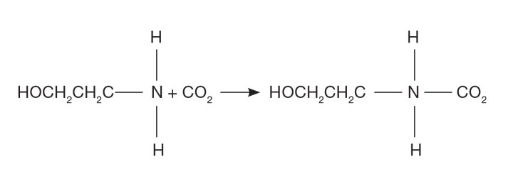
Energy requirements are principally associated with the stripper reboiler, where energy is required to break the amine bond, vapourise water and add sensible heat to bring the rich MEA to reboiler temperature.
There are a range of variables to be optimised to reduce the power load, including:
- amount of CO2 to be captured;
- stripper reflux ratio;
- condensing temperature;
- stripper pressure;
- lean MEA circulation rate and aqueous concentration;
- reboiler temperature;
- lean/rich exchanger temperature approach; and
- packing height.
Years of design and operational experience indicate that an energy-efficient MEA plant would deliver a metric of around 3.5 MJ/kg CO2 absorbed.3
Split flow
Energy savings can be made by deploying a split flow amine system (see Figure 4). Partly-regenerated amine solution is taken from the middle of the stripper to the middle of the absorption column. With this arrangement the semi-lean amine absorbs most of the CO2, which results in a reduced reboiler duty. Reboiler savings of around 0.3 MJ/kg CO2 have been reported.4 It does though come at a cost for additional plant.

Low heat of absorption
A large portion of the energy required for absorption and regeneration lies in the breaking of the amine CO2 bond. Energy savings could be made if an alternative solvent with a lower heat of absorption was used.
This has been the subject of much research and development. Mitsubishi Heavy Industries (MHI) has developed a proprietary amine solvent, KS-1. MHI claims a metric of 2.5 MJ/kg of CO2 captured5 – a very significant 40% saving over conventional MEA.
In the UK, C-Capture is moving ahead with a non-amine based solvent. Trials are ongoing at the Drax power station. The developers claim6 a metric of 1.5–2.0 MJ/kg – a bit of a game changer if it can be commercialised.
CO2 compression
Integrally-geared compressors are typically used for CO2 compression. These are multi-shaft machines where several pinion shafts, with two impellers each, are arranged around a central bull gear. The impellers are of differing sizes, usually a mixed flow design, and the gearing allows for optimal specific speed and maximum efficiency. Impellers are of overhung design fitted with adjustable inlet guide vanes to help maintain efficiency during turndown conditions.
For any centrifugal machine, hydraulic efficiency is affected by:
- disc friction (secondary vortex between outer surface of impeller and casing);
- surface roughness;
- leakage (backflow from discharge through seating gaps); and
- mixing losses (flow direction changes).
Since CO2 compression is often the largest contributor to the parasitic energy loss, it goes without saying that high efficiency machines should be selected.
A 5-stage compression system with aftercooling was modelled to illustrate some energy saving opportunities. The base case used was:
CO2 flow = 1 kg/s
Suction pressure = 1.50 bar
Discharge pressure = 120 bar
Aftercooler temperature = 30oC
Pressure drop between stages = 1 bar
Polytropic efficiency = 75%
Base case CO2 compression requirements were calculated as 400 kW.
Instead of a 1 bar loss between stages, a 0.5 bar loss was simulated which resulted in a power requirement of 375 kW – a 6% saving.
Raising the first-stage suction pressure to 2.5 bar yielded a requirement of 355 kW – an 11% saving. The suction pressure of the first-stage compressor will be dictated by the operating pressure of the amine stripper. This highlights the need for the full system to be considered when evaluating energy efficiency. If the amine system has a different designer to the compression system there is a clear need for both designers to integrate their solutions to provide an overall minimum CCS parasitic power load.
Increasing compressor efficiency to 80% polytropic produces a power requirement of 375 kW – a 6% saving.
Reducing aftercooler outlet temperatures to 25oC resulted in a 390 kW power saving requirement – a 2.5% saving.
When all of the above sensitivities are combined, the power requirement reduces to 300 kW – a 25% saving.
Like many energy-saving opportunities there will be an associated increase in capital cost – reduced pressure losses will require increased pipe/vent sizes and larger heat exchangers. Increased compressor efficiency will increase the cost of the machine. The increased cost has to be balanced against the energy saved.
Ramgen compressor
Jointly funded by the US Department of Energy and Dresser Rand, the Ramgen shockwave compressor7 has been described as a game changer for CO2 compression.
The Ramgen compressor uses the same principle as supersonic jet engines. A high-speed rotating disk with a raised v-shaped section creates a ramming effect on CO2 that has been introduced into an annular space between the disk and the compressor casing. The CO2 velocity is increased to around Mach 2 on the upward path, as the CO2 decelerates on the expanding diffuser side of the disc the pressure increases. Compression ratios of 10:1 can be achieved; much higher than the 2-3:1 typically provided by each stage of the integrally geared, centrifugal compressor. As a result of minimising aerodynamic leading edges, the Ramgen compressor minimises drag, thus delivering high efficiencies. A schematic of the compression process is shown in Figure 5.

Because the Ramgen can develop much higher pressures from a single stage, only two stages would be required instead of the five for the integrally-geared machine. The integrally-geared and Ramgen pressure enthalpy profiles are shown in Figure 6.
It is evident that with a 10:1 compression ratio, the Ramgen will produce much higher outlet temperatures. In addition to the improved efficiency of the Ramgen compressor, these high temperatures offer a further energy saving – by utilising the heat of compression for the amine reboiler.

A model was prepared to raise 3.5 bar steam from the heat of compression to supplement the amine reboiler. Calculations for the available heat of compression suggest a value of 0.4 MJ/kg CO2 can be made available for reboiling – thus providing a reboiler energy saving of the order of 15% from the current 2.5 MJ/kg CO2 offered by MHI and its KS-1 solvent. The Ramgen is a case where a new design can offer both capital and energy savings. Whether the CCS designers make use of the Ramgen remains to be seen.
Read the previous articles in this series:
Energy Saviours Part 1
Energy Saviours Part 2
Energy Saviours Part 3
Energy Saviours Part 4
Further reading
1. https://bit.ly/3gnDUn4
2. https://bit.ly/2BVMWIY
3. https://bit.ly/2XoVtfe
4. https://bit.ly/3iaxNTN
5. https://bit.ly/30tWKnb
6. https://bit.ly/39RVvRM
7. https://bit.ly/2PQNqUj
Recent Editions
Catch up on the latest news, views and jobs from The Chemical Engineer. Below are the four latest issues. View a wider selection of the archive from within the Magazine section of this site.


